OpenGL: Making a 2D Grid Image
There are sometimes that you may need to create a gridded image. Images created using grids allow you to do various effects on images, like the famous wave effect, or a ripple effect. I will not show you the way of performing the wave effects, but I will try to point you in the right direction of creating the grid behind the image.
Note that I will try to comply with the general rules as much as possible. The code I will give you will work on PCs, Macs, and Mobile Devices that run on top of OpenGL. I will try to stay away from platform-specific instructions as much as possible.
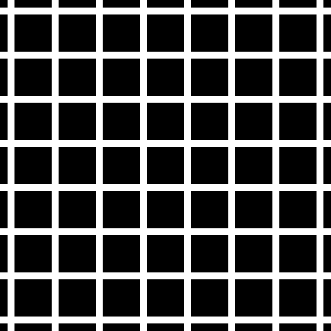
The following image represents the grid as it will be created without the image being applied onto it.
First of all, lets create the necessary variables that will hold our image grid.
int verticalDivisions;
int horizontalDivisions;
GLfloat *verticesArr;
GLfloat *textureCoordsArr;
GLuint textureID;
The first two variables will hold the image grid’s size in divisions. In the above image vertical divisions are 4, and the vertical ones are 8. As you can see, more divisions have more memory usage, and tend to behave slower.
The last 2 variables are arrays that will hold the vertex and texture coordinates data correspondingly.
TextureID will hold the image texture ID. Note that the image should be square, to comply with OpenGL versions prior to 2.0
Loading the texture should be an easy task, and I won’t mention it here. I use Quartz 2D rendering methods to load the textures, but you can use whatever you want. I continue this tutorial, having taken for granted that you have already loaded your texture and connected it with textureID.
Step one: Allocate Memory
Memory allocation is made using the verticalDivisions and horizontalDivisions.
For the mesh: For each vertical division you have 2 vertices, with 3 floats each one, describing the x,y and z values. So, for each vertical division, you will have 6 GLFloats. However, after the first triangle is created, you only need 1 more vertex to create a new square half.
For the texture coordinates: The same as above, only that you need 2 GLFloats instead of 3 since there is no z value in the texture coordinates.
verticalDivisions = vertDiv;
horizontalDivisions = horDiv;
unsigned int verticesArrsize = (vertDiv * ((2 + horDiv * 2) * 3));
unsigned int textureCoordsArraySize = vertDiv * ((2 + horDiv * 2) * 2);
verticesArr = (GLfloat *)malloc(verticesArrsize * sizeof(GLfloat));
textureCoordsArr = (GLfloat*)malloc(textureCoordsArraySize * sizeof(GLfloat));
if (verticesArr == NULL) {
    NSLog(@"verticesArr = NULL!");
}
Step 2: Populate Mesh
Here we create the actual mesh. kWindowHeight and kWindowWidth are constant values that you may want to change.
We create the mesh 2 vertices at a time, which means 6 GLFloats at a time. For each vertical division, we need 6 GLFloats. currWidth and currHeight hold the current width and height. Current width and height is the sum of the previews filled vertices. We need those counters to use the offset where we will create new vertices.
For the z value, we use 0.0f.
float height = kWindowHeight/verticalDivisions;
float width = kWindowWidth/horizontalDivisions;
int i,j, count;
count = 0;

for (j=0; j<verticalDivisions; j++) {
    for (i=0; i<=horizontalDivisions; i++, count+=6) {
        //2 vertices each time...
        float currX = i * width;
        float currY = j * height;
        verticesArr[count] = currX;
        verticesArr[count+1] = currY + height;
        verticesArr[count+2] = 0.0f;
        verticesArr[count+3] = currX;
        verticesArr[count+4] = currY;
        verticesArr[count+5] = 0.0f;
    }
}
int cnt;
for (cnt=0; cnt3 ) {
    printf("count: %i, Coords: %f, %f, %f,n",cnt, verticesArr[cnt],verticesArr[cnt+1],verticesArr[cnt+2]);
}
Step 3: Populate Texture Coords
In this occasion, we use the same approach as above. Only that now there are 4 vertices per division. Since 1.0f is the maximum value for a textures coordinates’ width or height, we divide 1.0f with the horizontal and vertical divisions to find the offset of the newly created texture coordinates.
float xIncrease = 1.0f/horizontalDivisions;
float yIncrease = 1.0f/verticalDivisions;

int x,y,count;
//int elements;
count = 0;

for (y=0; y<verticalDivisions; y++) {
 for (x=0; x<horizontalDivisions+1; x++, count+=4) {
 float currX = x *xIncrease;

 float currY = y * yIncrease;
 textureCoordsArr[count] = (float)currX;
 textureCoordsArr[count+1] = (float)currY + yIncrease;

 textureCoordsArr[count+2] = (float)currX;
 textureCoordsArr[count+3] = (float)currY;
 }
}

int cnt;
int cnt2 = 0;
NSLog(@"expected %i vertices, and %i vertices were done",(verticalDivisions * ((2 + horizontalDivisions*2 ) * 2) ) , count );
Step 4: Draw
Since we have everything set up, it’s time to draw the grid with the image.
glBindTexture(GL_TEXTURE_2D, textureID);
glClearColor(0.0f, 0.0f, 0.0f, 1.0f);
glClear(GL_COLOR_BUFFER_BIT);

glEnableClientState(GL_VERTEX_ARRAY);
glEnable(GL_TEXTURE_2D);
glEnableClientState(GL_TEXTURE_COORD_ARRAY);
glTexCoordPointer(2, GL_FLOAT, 0, textureCoordsArr);
glVertexPointer(3, GL_FLOAT, 0, verticesArr);
glPushMatrix();
{
    int i;
    for (i=0; i<verticalDivisions; i++) {
        glDrawArrays(GL_TRIANGLE_STRIP, i*(horizontalDivisions*2+2), horizontalDivisions*2+2);
    }
}
glPopMatrix();

glDisableClientState(GL_VERTEX_ARRAY);
glDisableClientState(GL_TEXTURE_COORD_ARRAY);
glDisable(GL_TEXTURE_2D);
With this image grid, you can apply many advanced effects, like the wave or the ripple effect. I used vertex arrays and triangles to make the grid, because I wanted to make the code compatible with OpenGL ES 1.0.
The code is usable, but not perfect. An updated version of this code with attention to detail and performance will be used in the new SFCocoa. To improve performance, you should use display lists, or indexed arrays.